Lec 21 · Interconnection network(상호연결망): topology 와 flow control
정밀 정리 · 검증 2026-09-24 10:46
1개요
1.1과목 마지막 주제인 interconnection network 의 첫 강의. lossless network 를 가정한다.
1.2성능 지표(throughput, zero-load latency = head + serialization)와 diameter·bisection bandwidth 를 정의한다.
1.3topology: bus/crossbar, torus·mesh(k-ary n-cube), ring, tree·fat tree, butterfly, Clos, irregular.
1.4flow control: circuit switching → store-and-forward → virtual cut-through → wormhole → virtual channel. credit(p49~52)은 다음 강의.
2섹션별 정리 상황·문제 → 원인 → 해결
2.10:34–7:19Interconnection network(상호연결망) 정의와 규모
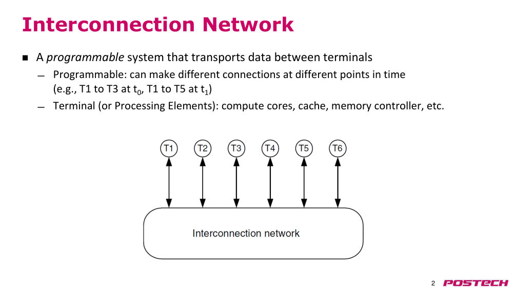
상황·문제terminal(CPU core, cache, memory controller, node) 사이 data 를 옮기는 programmable 시스템이 필요하다. 시점마다 다른 연결(T1→T3, 이후 T1→다른 node)을 만든다.
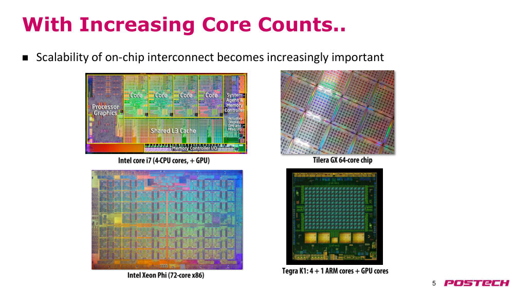
원인single-core 성능 scaling 이 멈춘 뒤 multi-core 가 보편화되어 on-chip interconnect 의 scalability 가 중요해졌다.
해결LAN/WAN 과 개념은 같지만 time scale·요구가 달라 trade-off 가 다르다. 이 강의는 packet 이 사라지지 않는 lossless network 를 가정한다.
- 인터넷은 packet loss 를 TCP/IP 가 복구하지만 여기서는 loss 가 없다고 가정
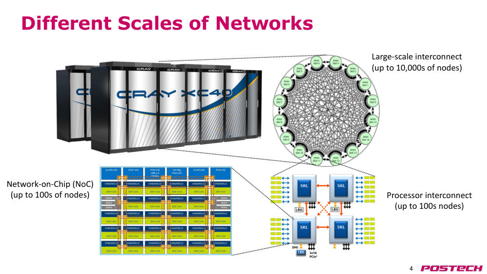
- 규모: NoC(수백 node) · processor interconnect(QPI/UPI) · large-scale(수천 node)
- Tilera 64-core, Xeon, mobile AP 모두 NoC 사용
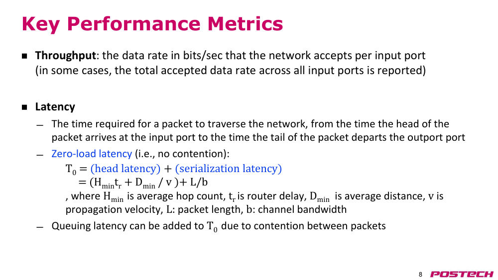
2.27:19–17:05용어와 핵심 성능 지표: throughput·latency
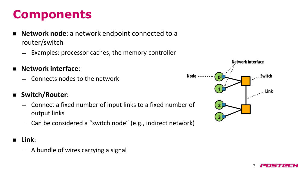
상황·문제network node, network interface, switch/router, link 의 역할을 정하고 성능을 무엇으로 잴지 정한다.
원인latency 는 head 가 input port 에 도착한 시점부터 tail 이 output port 를 떠날 때까지로, contention 여부에 따라 달라진다.
해결zero-load latency T0 = head latency(H_min·t_r + D_min/v) + serialization latency(L/b). contention 이 있으면 queuing latency 가 더해진다.
- throughput: input port 당 수용 data rate(bits/s, flits/cycle). 제품 발표의 수 TB/s 는 전체 합일 가능성
- head latency 는 topology·routing, serialization 은 packet 길이에 비례
- switch 는 고정 개수 input link 를 고정 개수 output link 에 연결
2.317:05–23:27Path diversity 와 latency–throughput 곡선
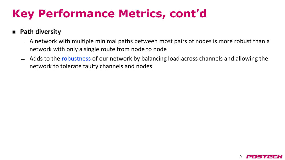
상황·문제source–destination 사이 경로가 하나면 link 하나 고장으로 두 node 가 끊기고 contention 을 피할 수 없다.
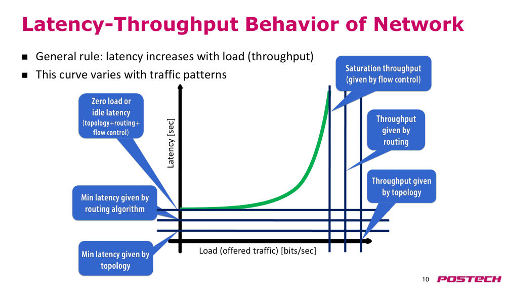
원인network 성능은 load(injection rate) 와 traffic pattern 에 따라 달라지며, steady state 에서 측정해야 한다.
해결여러 minimal path 로 load balancing·fault tolerance 를 얻는다. 곡선의 y 절편이 zero-load latency, 수직 점근선이 saturation throughput.
- topology 가 최소 latency·최대 throughput 을 정하고 routing·flow control 이 그 위에 손실을 더함
- saturation 이상 load 에서는 latency 가 무한히 증가
- flow control A/B 처럼 곡선을 겹쳐 비교
2.423:27–30:06ICN 구성 측면과 topology 지표 (diameter, bisection)
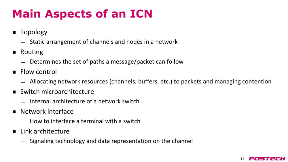
상황·문제topology, routing, flow control, router microarchitecture, network interface, link architecture 를 구분해 설계한다.
원인uniform random(all-to-all) traffic 의 지속 가능 throughput 은 network 을 반으로 나눈 cut 의 bandwidth 에 막힌다.
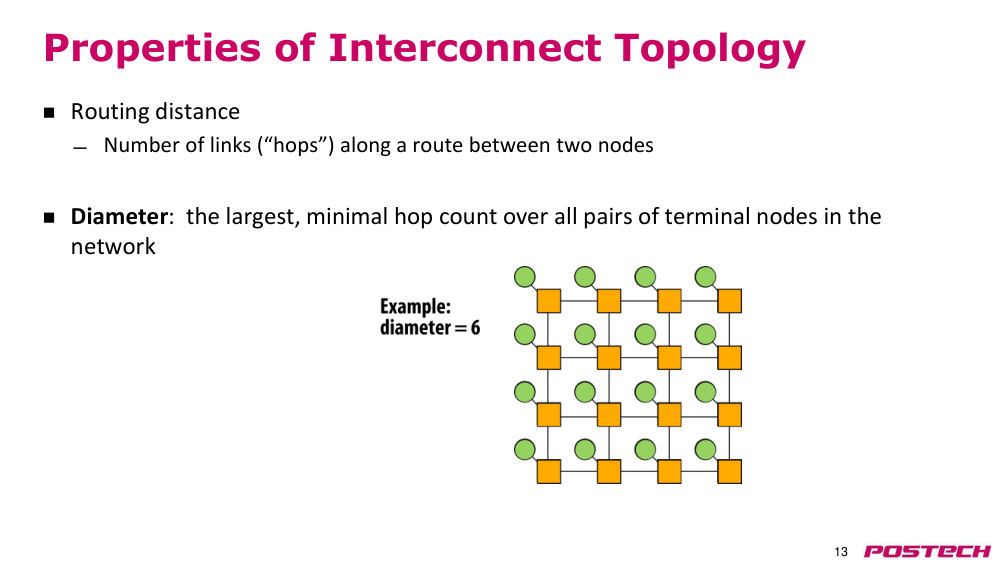
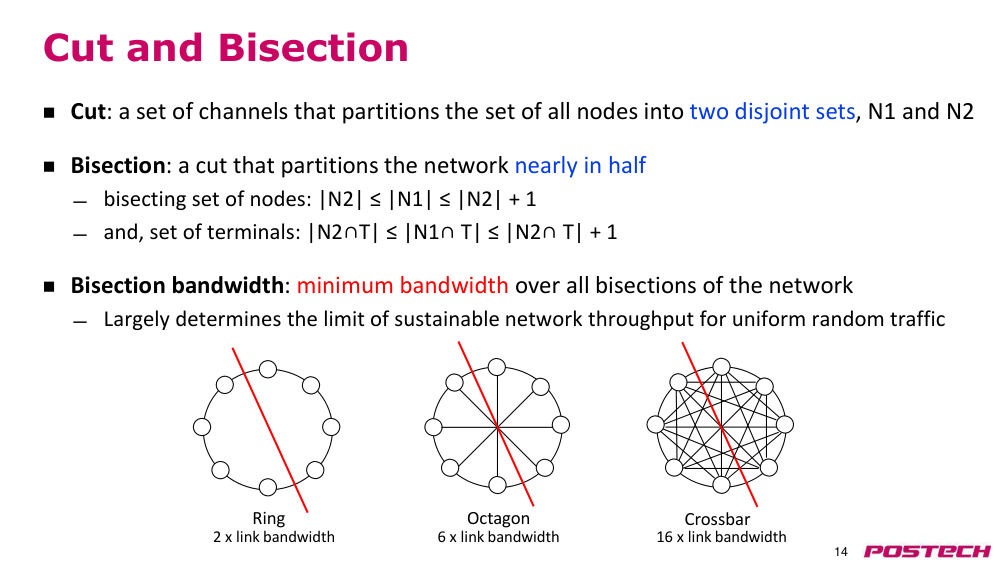
해결direct(모든 router 에 terminal) / indirect topology 구분, diameter = 모든 terminal 쌍 minimal hop count 중 최대, bisection bandwidth = 모든 bisection 중 최소 bandwidth.
- bisection: 두 집합 node 수가 같거나 1 차이
- 예: ring 2×, octagon 6×, crossbar 16× link bandwidth (p14)
- slide 13 예시 network diameter = 6 hop
2.530:06–32:49Bus 와 crossbar
상황·문제switched topology 의 대안으로 bus 와 crossbar 가 있다.
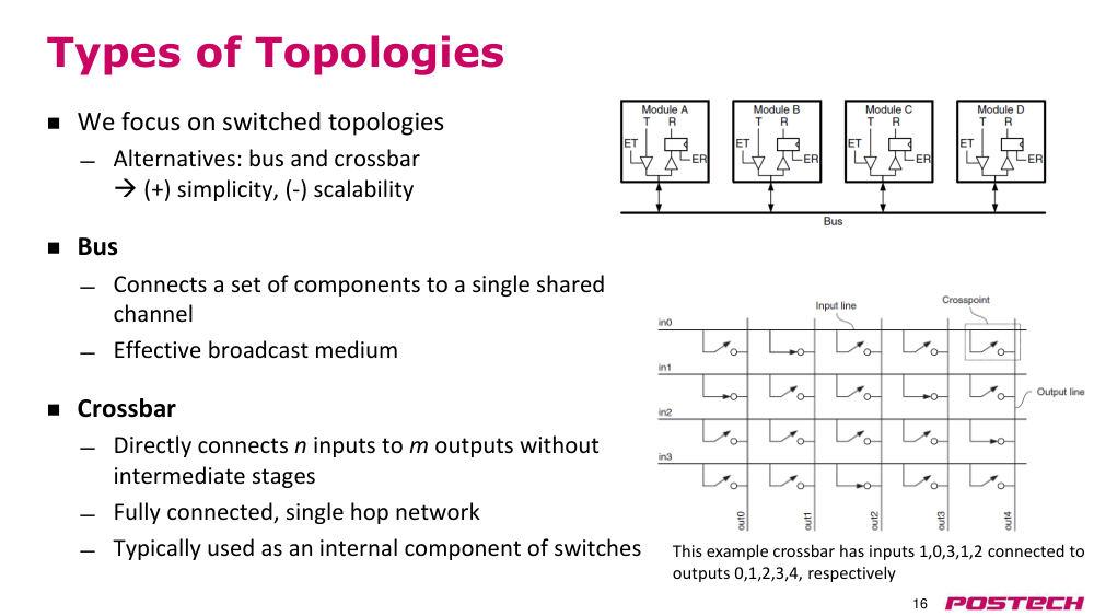
원인bus 는 단일 공유 channel 이라 한 번에 한 source 만 broadcast, crossbar 는 n×m 직접 연결이라 비용이 크다.
해결둘 다 단순하지만 scalability 가 낮다. crossbar 는 주로 switch 내부 부품으로 쓰이고, 강의는 switched topology 에 집중한다.
- crossbar: fully connected single-hop, 여러 source–destination 동시 연결
2.632:49–39:22Torus·mesh (k-ary n-cube) 와 hypercube
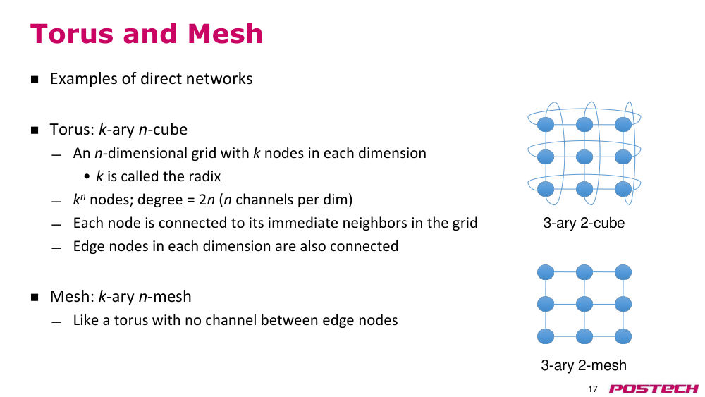
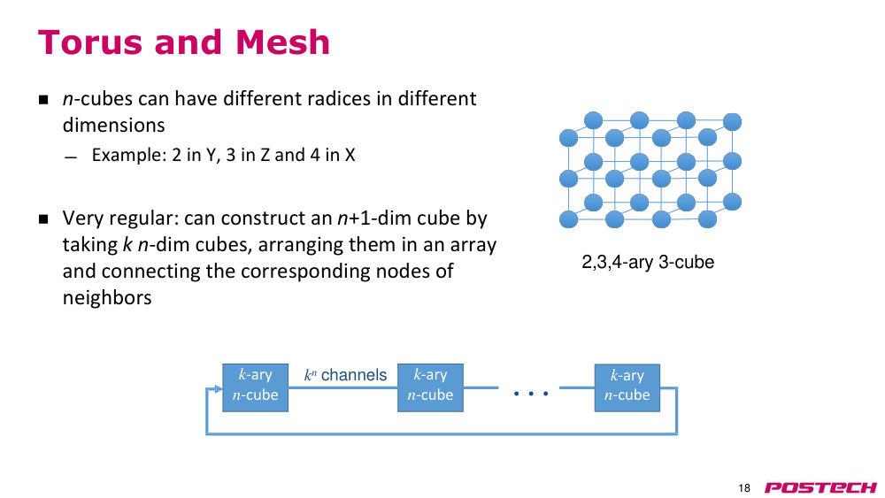
상황·문제규칙적인 direct network 로 torus(k-ary n-cube)와 mesh(k-ary n-mesh)를 쓴다. k=radix(dimension 당 node 수), n=dimension 수.
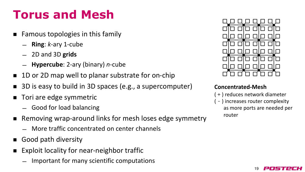
원인mesh 는 wraparound link 가 없어 edge symmetry 가 깨지고 traffic 이 중앙 channel 에 몰린다.
해결torus 는 edge symmetric 이라 load balancing 에 유리. k 개의 n-cube 를 이어 (n+1)-cube 를 만든다. concentrated mesh 는 router 당 terminal 여러 개로 router 수와 diameter 를 줄인다.
- ring = k-ary 1-cube, hypercube = 2-ary n-cube
- 1D/2D 는 on-chip 평면에, 3D 는 supercomputer 에 잘 맞음
- near-neighbor traffic(과학 계산)에 잘 맞고 path diversity 가 좋음
2.739:22–43:38Folded torus, hierarchical ring, 실제 사례
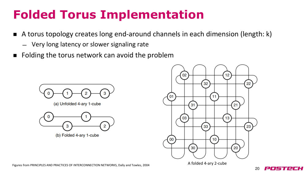
상황·문제torus 의 wraparound channel 은 길이 k 로 길어 signaling rate 를 낮추거나 일부 node 의 latency 를 키운다.
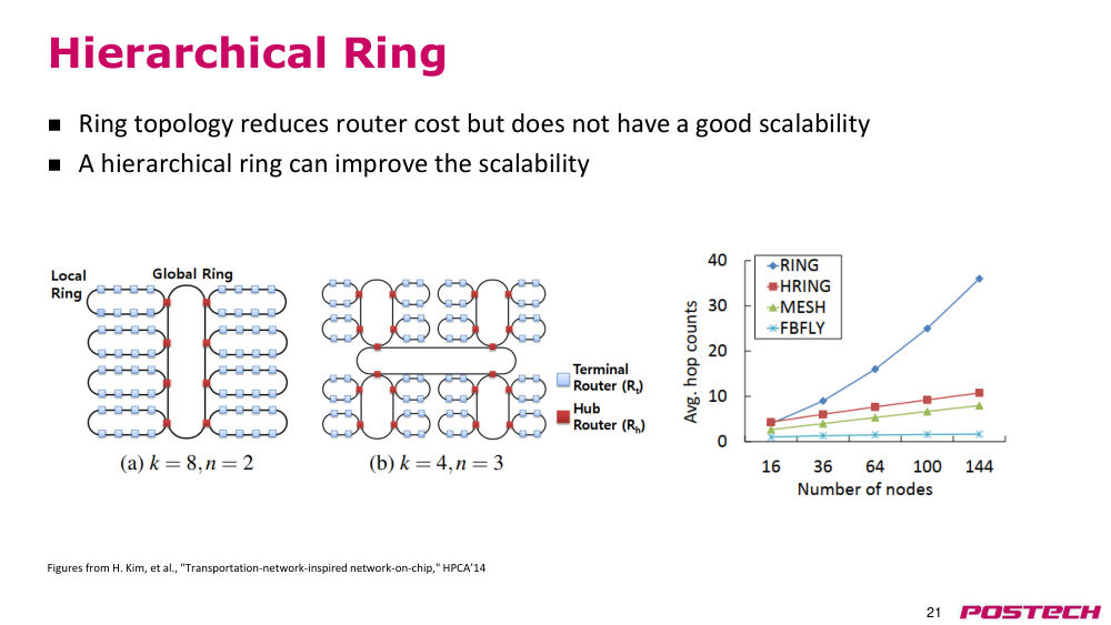
원인ring 은 router port 가 적어 싸지만 node 가 많아지면 hop count 가 크게 늘어난다.
해결folded torus 로 모든 link 길이를 비슷하게(mesh 대비 2배) 맞춘다. hierarchical ring 은 local ring 을 hub router 로 global ring 에 이어 scalability 를 높인다.
- link 가 mesh 보다 2배 길어지는 것이 on-chip 에서 mesh 가 더 흔한 이유 중 하나
- Intel CPU: ring(2009~2017+) → mesh(2017)
- Fugaku: 6D mesh/torus (Top500 1위, 슬라이드 2021)
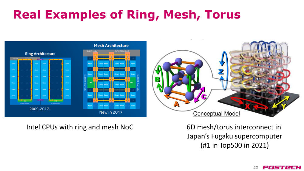
2.7.r.2Dally & Towles, Principles and Practices of Interconnection Networks (Elsevier) ↗ · 슬라이드 그림 출처이자 강의가 권한 교과서
2.843:38–50:45Tree, fat tree, butterfly
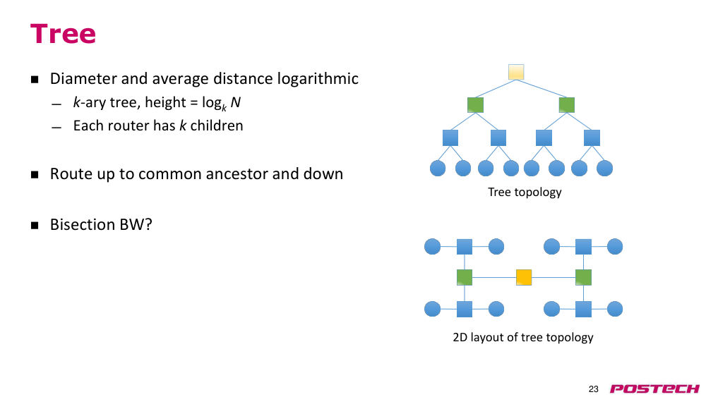
상황·문제tree 는 diameter 가 log_k N 으로 짧지만 root 근처 link 하나가 bisection 이 되어 bottleneck 이 된다.
원인tree 는 root 로 갈수록 bandwidth 가 줄고, butterfly 는 source–destination 쌍마다 path 가 하나뿐이다.
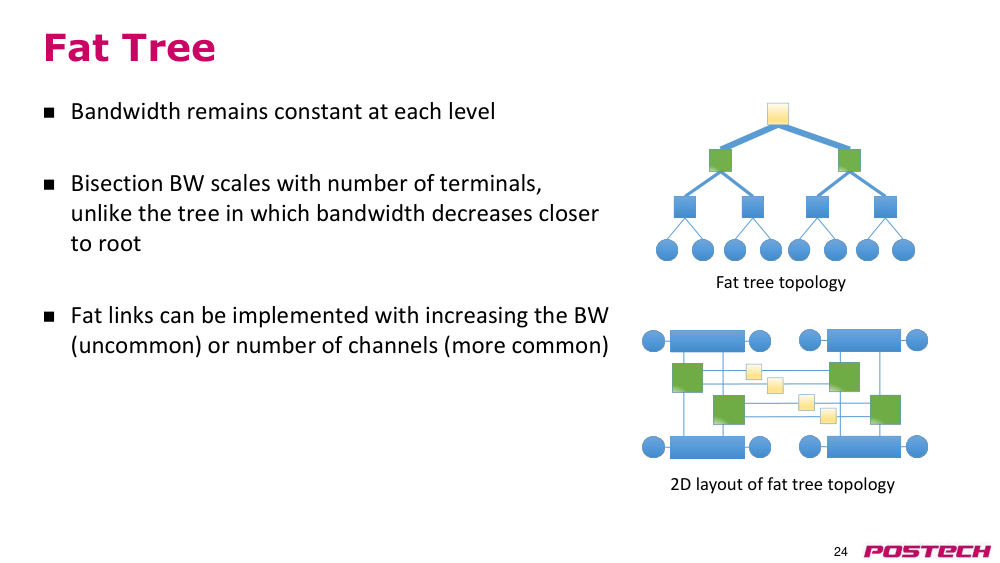
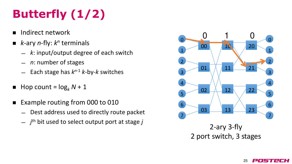
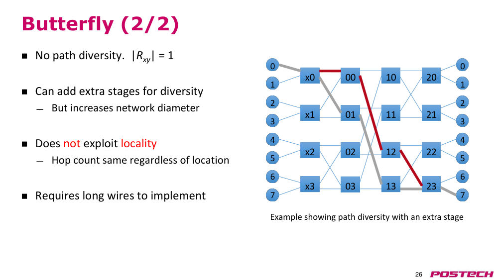
해결fat tree 는 level 마다 total bandwidth 를 같게(주로 link 수를 늘려) 유지한다. butterfly(k-ary n-fly)는 destination bit 로 stage 별 port 를 고르는 단순 routing.
- routing: 공통 조상까지 올라갔다 내려감
- 2-ary 3-fly: hop count = log_k N + 1 = 4로 고정
- butterfly 에 stage 를 더하면 path 는 늘지만 diameter 증가, locality 활용 못 함, 긴 wire 필요
2.950:45–54:27Clos network, folded Clos, irregular topology
상황·문제butterfly 와 달리 path diversity 가 있는 indirect network 가 필요하다.
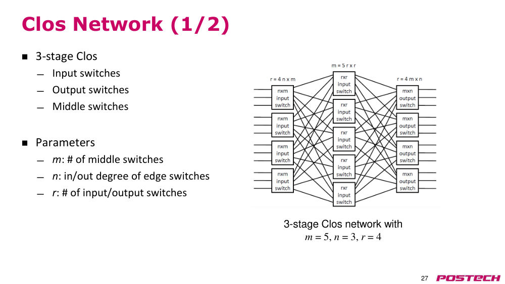
원인3-stage Clos 는 input/middle/output switch 로 구성되어 source–destination 쌍마다 middle switch 수(m)만큼 path 가 생긴다.
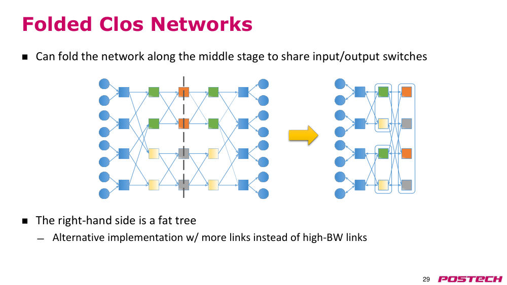
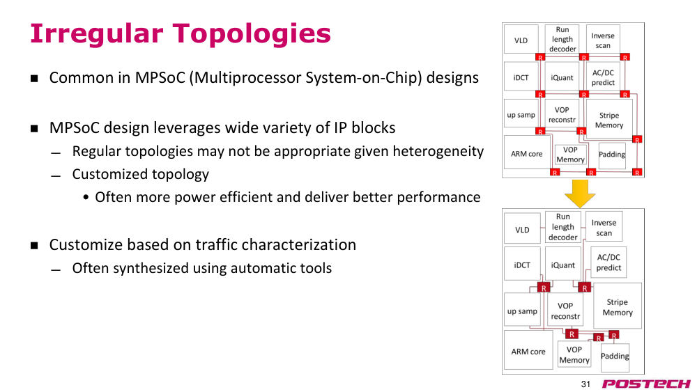
해결middle stage 를 다시 Clos 로 바꾸면 stage·diversity 증가. 가운데 선으로 접으면 fat tree 와 같다. heterogeneous IP 의 MPSoC 는 자동 tool 로 합성한 irregular topology 가 유리할 수 있다.
- |Rxy| = m
- 예: 3-stage Clos (m=5, n=3, r=4)
- omega, Benes, dragonfly 등은 교과서·논문 참고로 넘김
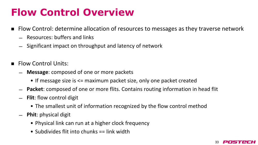
2.1054:27–1:00:54Flow control 개요: message·packet·flit·phit
상황·문제packet 이 contention 속에서 목적지에 도달하도록 buffer·link 를 할당하는 방식(flow control)이 필요하다.
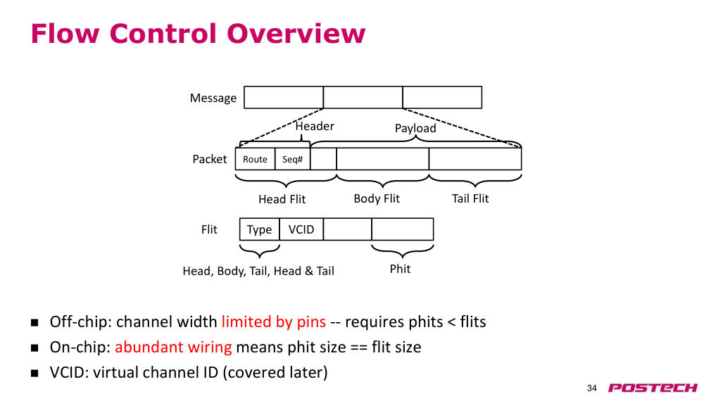
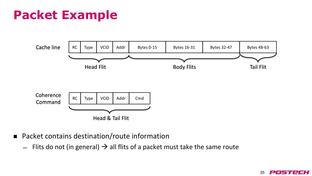
원인routing 정보는 head flit 에만 있어 body/tail flit 은 head 를 따라가야 하고, off-chip 은 pin 수로 channel 폭이 제한된다.
해결message → packet → flit(flow control 단위) → phit(physical 단위)로 나눈다. off-chip 은 phit < flit, on-chip 은 배선이 풍부해 phit == flit 이지만 buffer 면적이 비싸다.
- 예: 2-bit link 에 16-bit flit → phit 8개
- flit 의 type field(head/body/tail/head-tail) 와 VCID
- cache line 64B packet: head + body + tail flit
2.111:00:54–1:05:50Switching 분류와 circuit switching
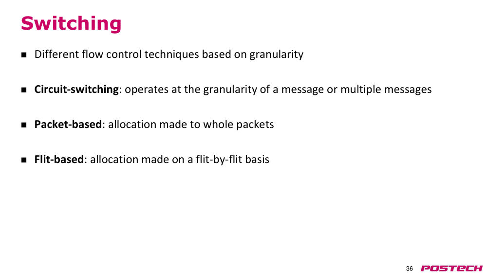
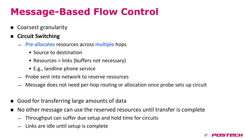
상황·문제flow control 은 allocation 단위로 circuit switching(message), packet 기반, flit 기반으로 나뉜다.
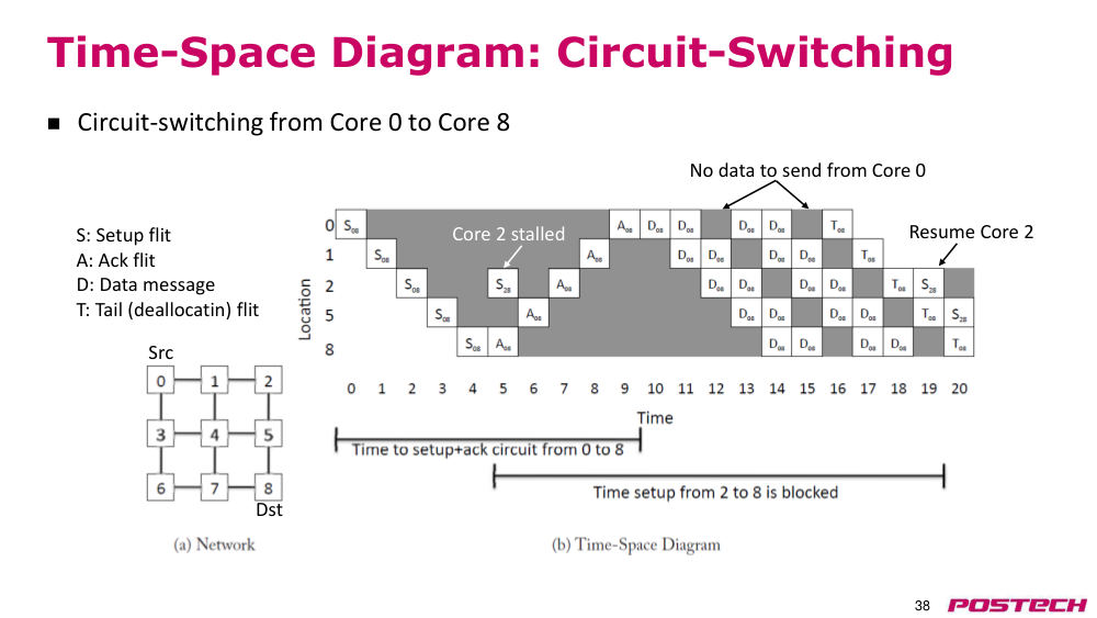
원인circuit switching 은 probe(setup flit)로 path 의 link 를 미리 예약하므로 다른 core 의 setup 이 막히고 link 가 놀 수 있다.
해결link 를 모두 예약해 buffer 가 필요 없고 hop 마다 routing 이 없다. data 가 크면 setup 비용이 무시되지만 아니면 자원 낭비.
- 예: core 0 → core 8, S(setup)·A(ack)·D(data)·T(tail) flit
- core 2 의 setup 이 막혀 stall 후 resume
- 비유 예: 유선 전화
2.121:05:50–1:09:37Packet 기반: store-and-forward 와 virtual cut-through
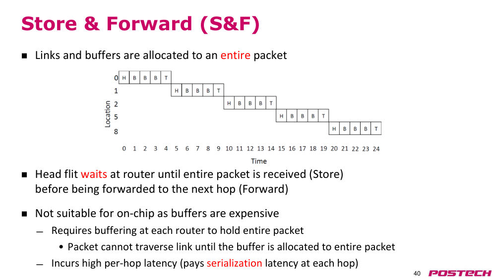
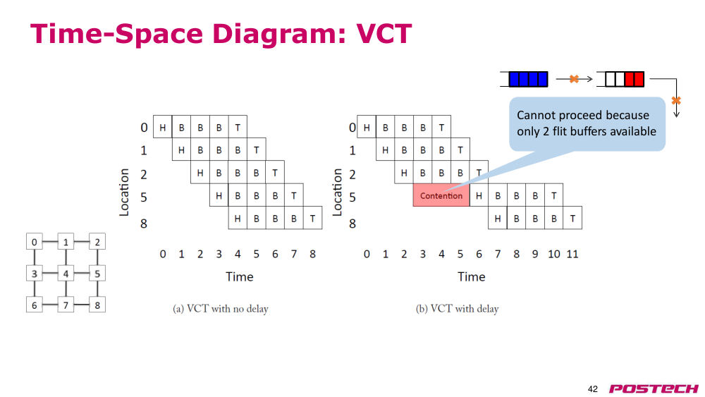
상황·문제packet 을 link 에 interleave 해 utilization 을 높이려면 in-flight packet 을 담을 buffer 가 필요하다.
원인store-and-forward 는 tail 까지 다 받은 뒤 전송해 hop 마다 serialization latency 를 치르고 큰 buffer 가 필요하다.
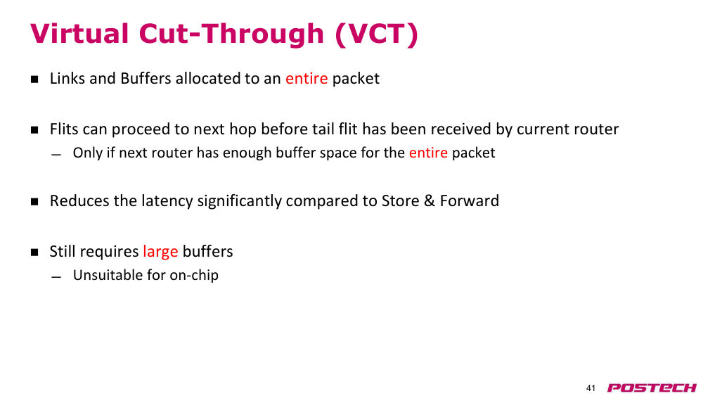
해결virtual cut-through 는 다음 router 에 packet 전체 공간이 있으면 tail 도착 전 전송해 latency 를 크게 줄인다. 다만 packet 단위 buffer 라 on-chip 에는 부적합.
- S&F 는 on-chip 에 부적합(buffer 비쌈)
- VCT: 2 flit 공간만 있으면 packet 전체가 못 들어가 진행 불가(p42)
2.131:09:37–1:15:31Wormhole flow control, HOL blocking, virtual channel
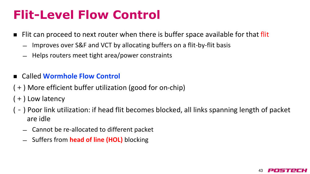
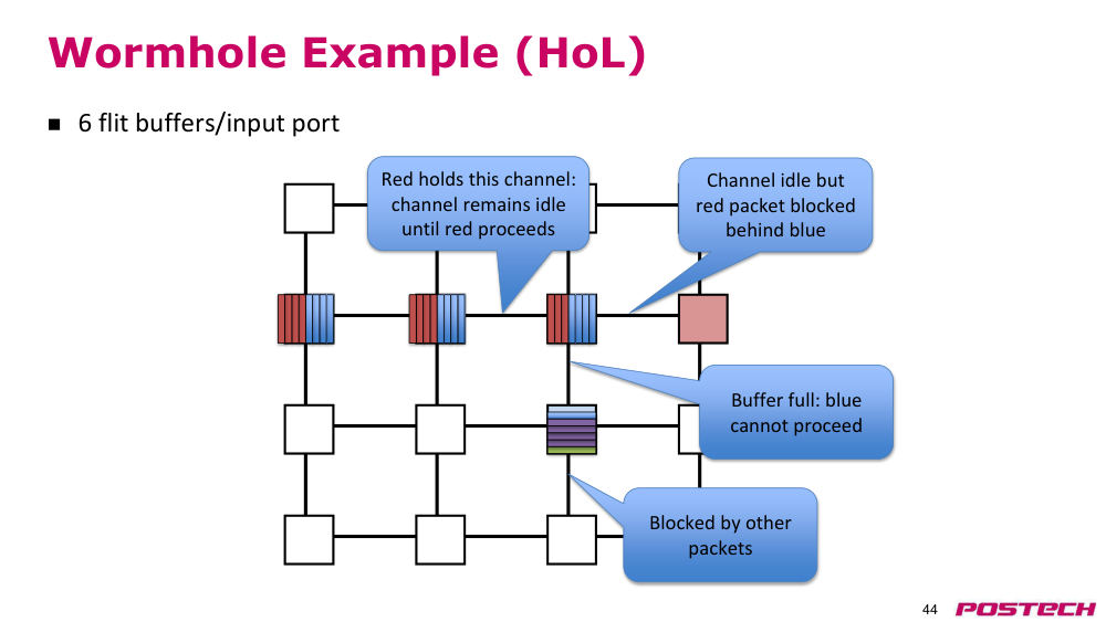
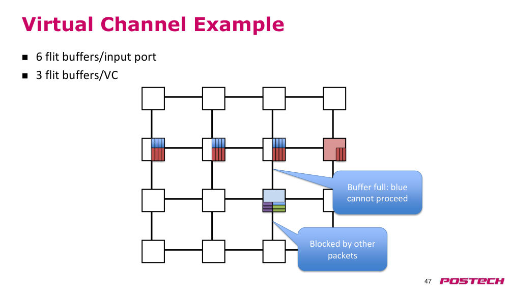
상황·문제flit 단위로 buffer 를 할당하면(wormhole) buffer 가 줄어 on-chip 에 맞지만 link utilization 이 나빠질 수 있다.
원인input port 당 queue 가 하나라 막힌 blue packet 뒤의 red packet 이 idle channel 을 못 쓴다(head-of-line blocking).
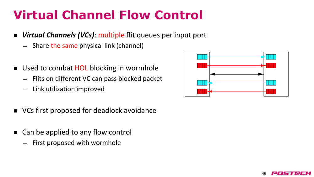
해결virtual channel: input port 당 flit queue 여러 개가 같은 physical link 를 공유해, 한 VC 가 막혀도 다른 VC 의 packet 이 진행한다.
- 예: 6 flit buffer/port → VC 2개 × 3 flit
- VC 는 원래 deadlock avoidance 용으로 제안(다음 강의)
- wormhole 은 VCT 의 낮은 latency 유지
2.141:15:31–1:17:31Flow control 기법 요약
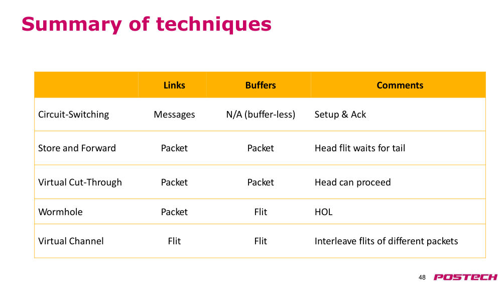
상황·문제다섯 기법을 link·buffer 할당 단위로 비교한다.
원인circuit: message/buffer 없음, S&F·VCT: packet/packet, wormhole: packet/flit, VC: flit/flit.
해결buffer backpressure·credit 기반 flow control(p49~52)은 다음 강의로 넘겼다.
- wormhole 의 약점 HOL 을 VC 가 flit interleave 로 해결
3핵심 개념
3.1zero-load latency(무부하 지연)
contention 없을 때 latency. T0 = H_min·t_r + D_min/v + L/b
3.2serialization latency(직렬화 지연)
head 가 나간 뒤 나머지 packet 이 빠져나가는 시간 L/b
3.5bisection bandwidth(이등분 대역폭)
network 을 절반으로 나누는 모든 cut 중 최소 bandwidth. uniform random traffic throughput 한계
3.6k-ary n-cube(torus)
dimension 당 k node, n dimension, wraparound link 포함. 없으면 k-ary n-mesh
3.7fat tree(팻 트리)
level 마다 total bandwidth 를 같게 해 root bottleneck 제거
3.8k-ary n-fly(butterfly)
k^n terminal, n stage, destination bit 로 routing, path 하나뿐
3.9Clos network(클로스 네트워크)
input/middle/output switch, path 수 = middle switch 수 m. 접으면 fat tree
3.10flit / phit
flit: flow control 단위, phit: physical 전송 단위. on-chip 은 phit == flit
3.11virtual cut-through(가상 컷스루)
다음 router 에 packet 전체 공간이 있으면 tail 도착 전 전송
3.12wormhole flow control(웜홀)
flit 단위 buffer 할당. buffer 가 적지만 HOL blocking 발생
3.13head-of-line blocking(HOL)
queue 앞의 막힌 packet 때문에 뒤 packet 이 idle channel 을 못 씀
3.14virtual channel(가상 채널)
input port 당 여러 flit queue 가 physical link 공유. 원래 deadlock avoidance 용
4스스로 확인
4.1zero-load latency 의 두 구성 요소는?
답
head latency(H_min·t_r + D_min/v)와 serialization latency(L/b)
4.2mesh 가 torus 보다 center channel 에 traffic 이 몰리는 이유는?
답
wraparound link 가 없어 edge symmetry 가 깨지기 때문
4.32-ary 3-fly 에서 hop count 는?
답
log_2 8 + 1 = 4, 모든 source–destination 쌍에서 동일
4.4folded Clos 는 어떤 topology 와 같은가?
답
fat tree
4.5virtual cut-through 가 on-chip 에 부적합한 이유는?
답
buffer 를 packet 단위로 할당해 큰 buffer 가 필요하기 때문
4.6wormhole 의 HOL blocking 을 virtual channel 이 어떻게 줄이나?
답
port 당 queue 를 여러 개 두어 한 VC 가 막혀도 다른 VC 의 packet 이 같은 link 를 씀
5참고 자료
5.1Dally & Towles, Principles and Practices of Interconnection Networks (Elsevier) ↗ · 슬라이드 그림 출처이자 강의가 권한 교과서